Ham radio | Raspberry Pi | SDR | other tech stuff
Turn your Icom ID-4100A into an APRS digipeater

I previously made a tutorial about turning the Icom 705 into an APRS digipeater. That was a fun project, but a very expensive endeavor just to use it as a digipeater. I decided to look into getting my current mobile rig, the Icom ID-4100A, setup as a digipeater.
Unlike the 705, the ID-4100A does not have a built-in sound card. I reached out to the folks at DigiRig to inquire if their DigiRig Mobile would work with my radio. Not only did they confirm it would, but they graciously agreed to send me one with the cables for the ID-4100 if I would demonstrate it in various projects. So this is the first of hopefully many videos showing off the DigiRig Mobile.
These instructions are written for the ID-4100A, but it’s possible that they might also work with the ID-5100A and potentially other radios.
Gear
To get started, you will need the following hardware to get started.
(Note: Some of these links are affiliate links (Amazon, Digirig) that support my website and content creation at no additional cost to you.)
- Icom ID-4100A VHF/UHF transceiver (discontinued, but sometimes available used on sites like QRZ.com, QTH Swap and eBay)
- Raspberry Pi 4 Kit or Raspberry Pi 5 Kit (the kits includes the microSD card, case and power supply.)
Note: I tried this project on a Raspberry Pi Zero 2W but there were some extra steps and gear needed to make it work properly. So for now I’m recommending you get the Pi 4 or Pi 5 for this project. Also, if you have a Micro Center nearby, you can build out the Pi individually a bit cheaper than buying a kit. - Digirig Mobile (DRMOB) Logic Levels: Amazon | Digirig | DX Engineering | Gigaparts (includes cables) | HRO (includes cables)
- Digirig Icom RJ-45 Cable (ICOMRJ45MOBILE): Amazon | Digirig | DX Engineering | Gigaparts
- Digirig USB-A to USB-C cable (USB-AC): Amazon | Digirig | DX Engineering | Gigaparts
- RT-Systems USB-RTS05 (this will allow you to use the ID-4100A’s internal GPS): DX Engineering | HRO
I will be using this Pi in a headless environment. Basically that means that once I have it setup, it will not be connected to a keyboard or monitor. For the software, I’m going to be using the Raspberry Pi OS Lite 64-bit version. I find that it uses less resources on the Pi than using the full desktop operating system. The easiest way to install it is to use the Raspberry Pi Imager software. It is available for Windows, Mac and Linux.
I have another tutorial that shows how to install the Raspberry Pi OS Lite operating system if you’ve never done it before.
Raspberry Pi OS Lite 64-bit installation tutorial
Once you have the operating system installed, you can access it either via plugging it in to a keyboard and monitor or preferably remote into via SSH like I do in the video above. That will require you to know what the hostname or IP address of your Pi is. If you don’t want to mess with that, then just use a keyboard and monitor.
Note: Throughout this tutorial you will see commands in white with a black background. If you’re using SSH, you can just copy and paste these commands into the window and it will make things go a lot faster than typing everything in manually. Also, when you use the sudo command it will prompt you for your password.
Icom ID-4100A
If you’re planning on utilizing the internal GPS, you’ll need to change a few settings on the radio
- Menu – GPS – GPS Set – GPS Select – Internal GPS
- Menu – GPS – GPS Set – GPS Out – On
- Change VFO frequency to 144.390 (US) or whatever your APRS frequency is.
- Open the squelch by turning the squelch encoder at the bottom right all the way to the left.
The 2.5mm end of the orange RT Systems cable (RTS05) will plug into the data jack on the back of the radio. The USB end will plug into the Raspberry Pi.
The Digirig USB cable has a USB-C connector that goes into the Digirig Mobile. The other USB-A end plugs into the Raspberry Pi.
The Digirig RJ45 Icom cable has three connectors on it. The 3.5mm end by itself (coiled) goes into the black audio port on the Digirig Mobile. The non-coiled 3.5mm end goes into the speaker jack on the back of the radio. The RJ45 plugs into the front right of the radio normally where the microphone would go.
Raspberry Pi
Before we get started, we need to install any updates on the Raspberry Pi and then reboot the Pi.
sudo apt update && sudo apt upgrade -y && sudo reboot
Disable HDMI and audio jack
The only audio we need for this project is from the Digirig. These steps will disable the HDMI and headphone jack audio from interfering with the Digirig.
This command shows us the audio devices on the Raspberry Pi.
aplay -l
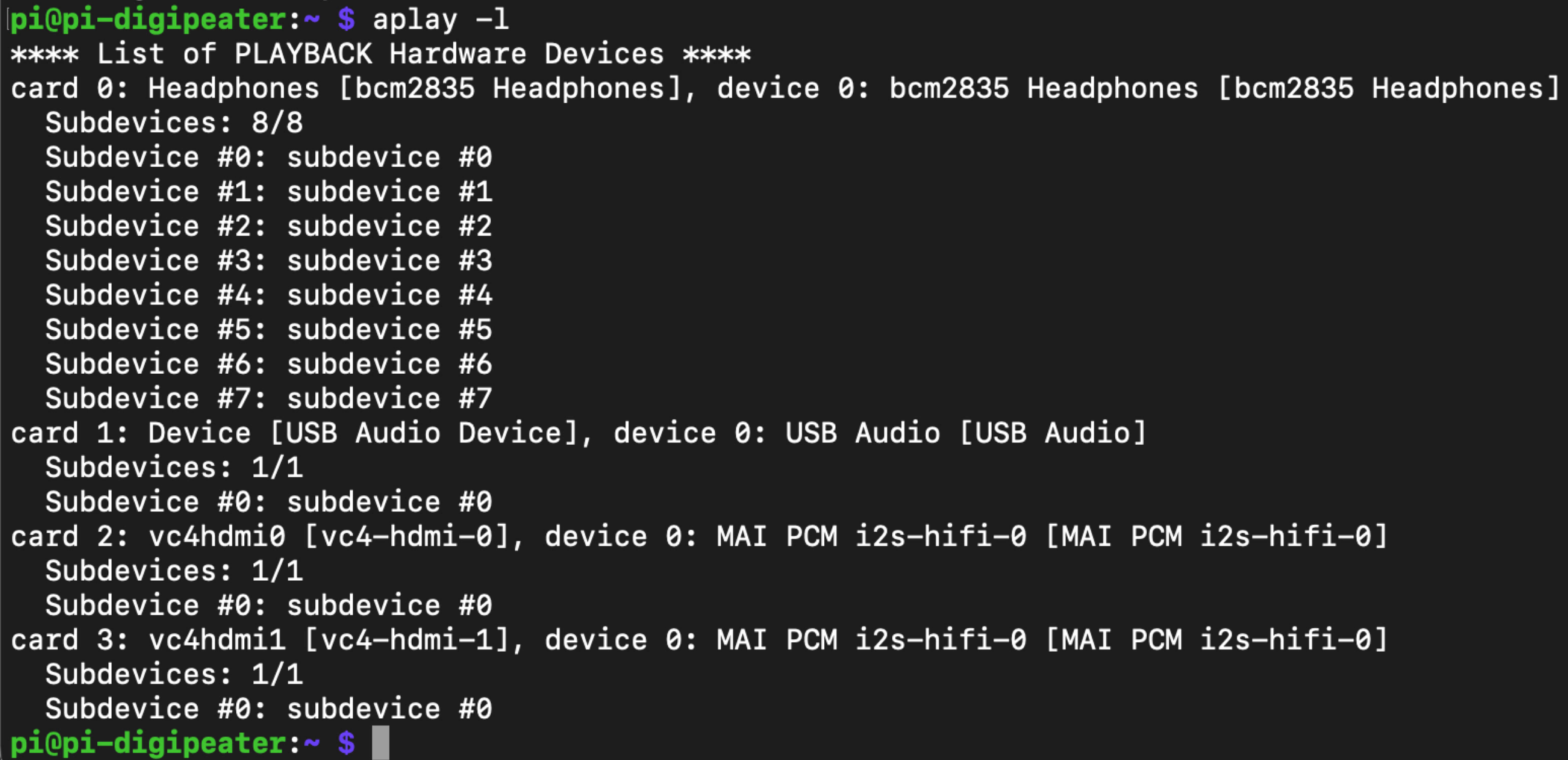
Open the Pi config file file to make the changes.
sudo nano /boot/firmware/config.txt
Arrow down until you see the line that says dtparam=audio=on. Change where it says on to off.
dtparam=audio=off
Next, go down to the line that says dtoverlay=vc4-kms-v3d. At the end of the line, type in ,noaudio.
dtoverlay=vc4-kms-v3d,noaudio
Do a CTRL-X, Y and then enter to save the file. Reboot the Pi.
sudo reboot
If all went well, you should only see the Digirig (USB Audio Device) when you run the following command.
aplay -l

Prerequisites
First we need to install some prerequisite programs to help us compile and install various programs for this project.
sudo apt install -y automake libtool texinfo git cmake libasound2-dev libudev-dev libavahi-client-dev tmux libgps-dev libncurses-dev gpsd chrony libgpiod-dev
Find device IDs
In order to communicate with the GPS and the DigiRig, we need to map out the device IDs.
ls /dev/serial/by-id
Assuming you only have the Digirig and RTS cable plugged into the Pi, you should see two devices. The names will vary slightly from my example below.
usb-RT_Systems_RTS05_Radio_Cable_RT60L8L1-if00-port0
usb-Silicon_Labs_CP2102N_USB_to_UART_Bridge_Controller_f888fb56f98dee1187fa01028acbdcd8-if00-port0
GPS
If you’re utilizing the ID-4100A GPS, we need to edit the config file to tell it where to find the GPS. First we need to move the current config to a backup file.
sudo mv /etc/default/gpsd /etc/default/gpsd.bak
Next we’re going to create a new config file.
sudo nano /etc/default/gpsd
Copy and paste the following text into the file.
START_DAEMON="true"
USBAUTO="true"
DEVICES="/dev/serial/by-id/usb-RT_Systems_RTS05_Radio_Cable_RT60L8L1-if00-port0"
GPSD_OPTIONS="-n"
Make sure to pay special attention to the DEVICES entry that it matches the device name from your RTS05 cable from the previous section.
Save the file with CTRL-X, Y and hit enter.
Now we need to restart the GPSD service.
sudo systemctl restart gpsd
If all went well, you should see a bunch of data when running the next command.
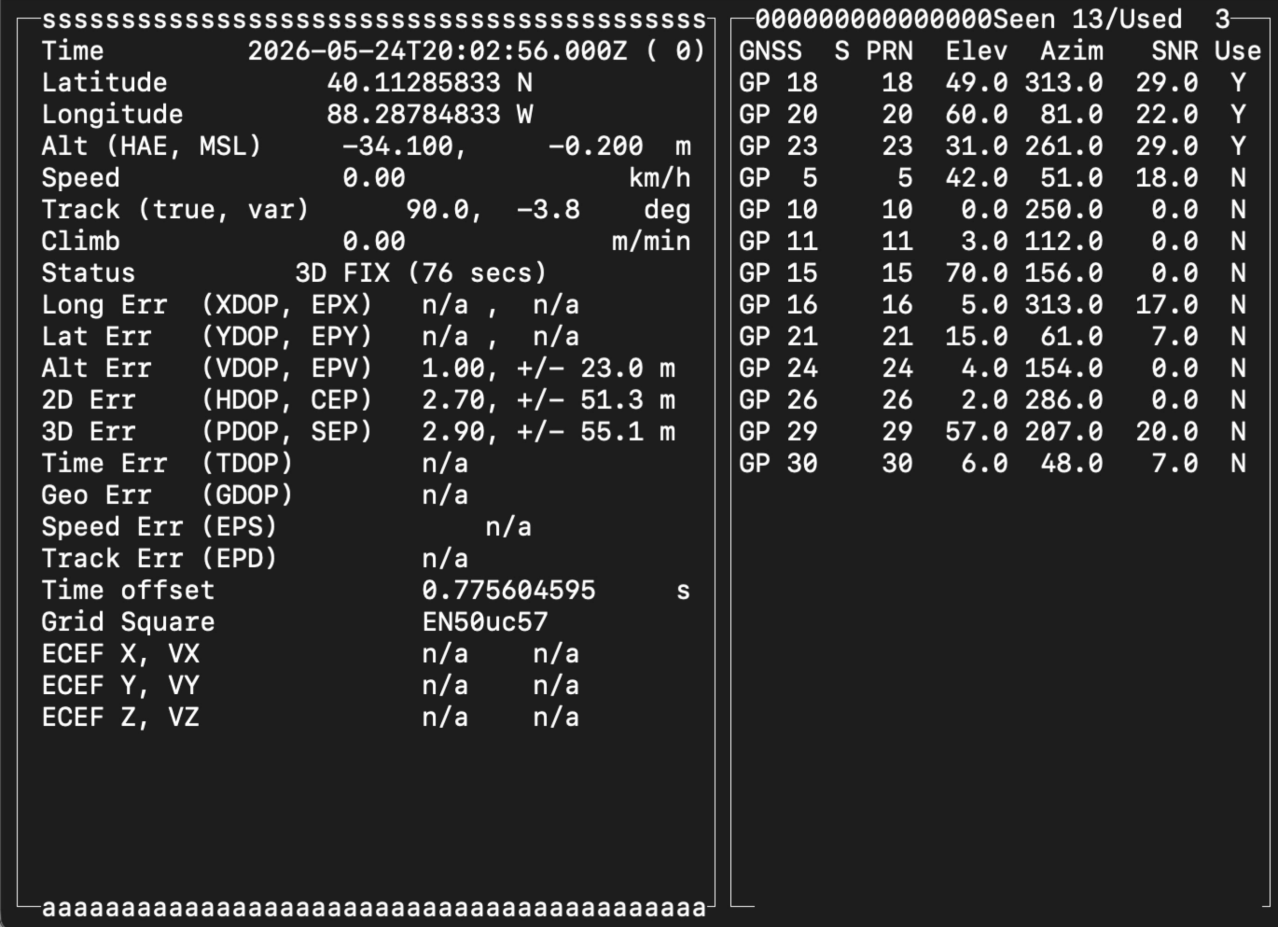
The data on the left is your specific date/time, location, elevation, time difference between the satellites and your Pi as well as your maidenhead grid square. On the right side is every satellite that your ID-4100A is seeing and how strong the signal of each one is. Pretty sweet! You can hit the Q button to quit out of cgps.
Note: You’ll need to either be near a window or outside to receive the GPS signals.
Chrony
Unless you have a Raspberry Pi 5, the Raspberry Pi does not come with a real-time clock built in. Usually this isn’t a problem because the Pi usually syncs the time from the internet when it boots up. However, if your Pi isn’t connected to the internet then it can’t update the date and time. That’s where the beauty of the GPS from the ID-4100A comes in. We can take the date/time from the satellites and use it to set the date and time of the Pi with no internet required.
To make this work, we need to edit the Chrony config file to tell it to use the GPS as a time source.
sudo nano /etc/chrony/chrony.conf
Copy and paste the following at the end of the file. Save the file by doing a CTRL-X, Y and Enter.
#GPS
refclock SHM 0 refid GPS poll 2
Restart the Chrony process for this to take effect
sudo systemctl restart chrony
Run this command to see if the GPS shows up in the list of sources.
chronyc sources
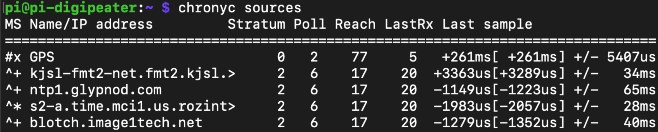
You should see the GPS at the top of the list. Depending on how many satellites you’re receiving, you should see a # and asterisk next to the GPS entry. This means you’re successfully syncing the date and time from the satellites. If you see a #x or #?, then you probably don’t have a good enough GPS signal to sync the time. This should work better with the radio outdoors with a clear view of the sky.
Direwolf
Now it’s finally time to install Direwolf which is the brains of the APRS operation. We will be compiling this from source code. Just run each command one at a time.
git clone https://github.com/wb2osz/direwolf
cd direwolf
mkdir build && cd build
cmake -DUSE_HAMLIB=0 ..
make -j4
sudo make install
make install-conf
cd
Now we need to configure Direwolf. To make things easier, we’re going to move the default configuration to a backup file.
mv /home/pi/direwolf.conf /home/pi/direwolf.bak
Next we’re going to create a new config file.
nano /home/pi/direwolf.conf
Now copy and paste the following into the file.
ADEVICE plughw:0,0
CHANNEL 0
MYCALL CALLSIGN
MODEM 1200
AGWPORT 8000
KISSPORT 8001
PTT /dev/serial/by-id/usb-Silicon_Labs_CP2102N_USB_to_UART_Bridge_Controller_f888fb56f98dee1187fa01028acbdcd8-if00-port0 RTS
DIGIPEAT 0 0 ^WIDE1-1$ ^WIDE1-1$
GPSD
TBEACON delay=1 every=30 symbol=1# via=WIDE2-1 comment="Portable W1-1 Digi"
The first thing is to look for the MYCALL line and change the call after it from CALLSIGN to whatever your callsign is. If you’re going to use an SSID then you would add it here. So if your call was W1AW and you wanted an SSID of 1, you would enter MYCALL W1AW-1.
Make sure you use your specific path that we ran earlier using the ls -la /dev/serial/by-id/ command for the line starting with PTT. (you want the one ending with -if00-port0)
Save the file by doing a CTRL-X, type Y and hit enter on the file name.
Now we need to setup Direwolf to start when the Pi boots up.
sudo nano /etc/systemd/system/direwolf.service
This is a new file so just copy and paste everything in the box below into the file. If you’re using a different home directory than the default Pi, then you’ll need to update this in the file. Once it’s in there, do a CTRL-X, type Y and hit enter for the file name to save.
[Unit]
Description=Direwolf
After=network.target

[Service]
Type=forking
#Modify the end of the line below to fit your own needs i.e path to your configuration file
ExecStart=/usr/bin/tmux new-session -d -s direwolf '/usr/local/bin/direwolf -c /home/pi/direwolf.conf'
Restart=always

[Install]
WantedBy=default.target
Now run the following command to enable the Direwolf service.
sudo systemctl enable direwolf.service
Reboot the Pi.
sudo reboot
After you log back into your Pi, run this command to show you what is happening with the digipeater.
sudo tmux attach -t direwolf
If everything worked correctly, you should see your digipeater retransmitting any WIDE1-1 traffic that it hears. If you see a warning in Direwolf saying GPS timeout, just give it a minute or two and then you should see something like “Location fix is now 3D”.
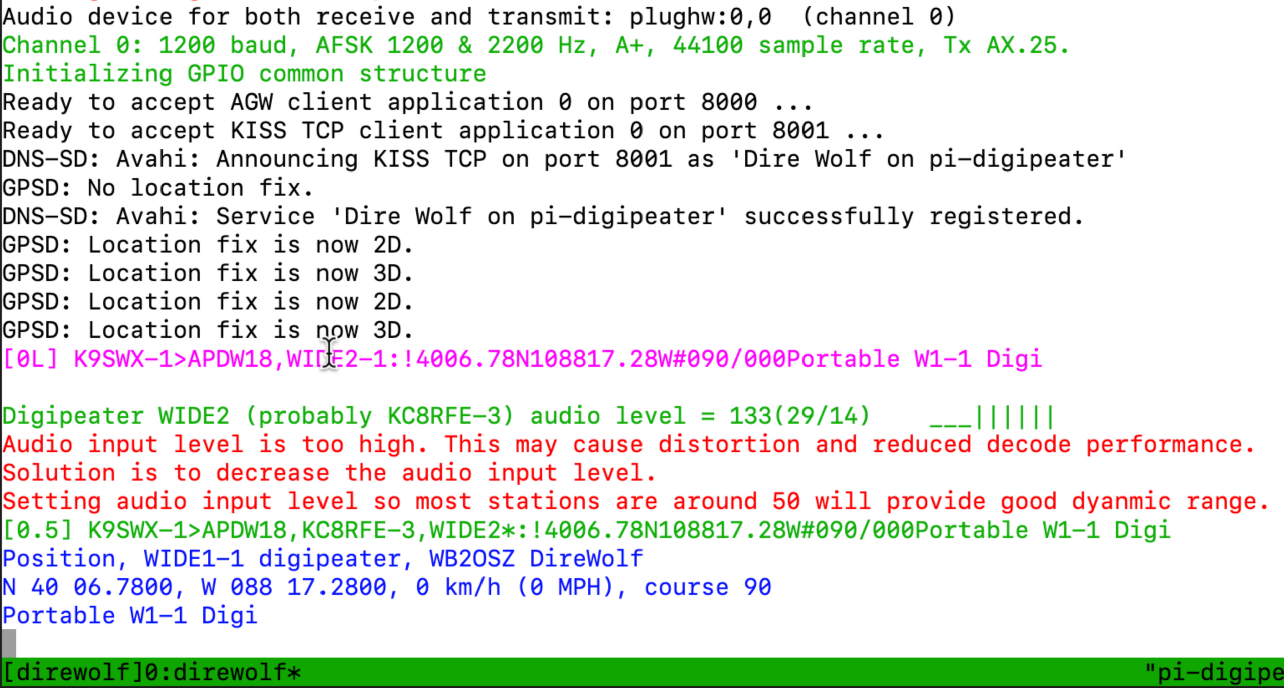
If you see a message that says “Audio input level is too high”, then you need to adjust the audio. Try turning down the volume on the radio just a bit and seeing what the packets say for audio. If that doesn’t work, check the sound card mixer levels.
alsamixer
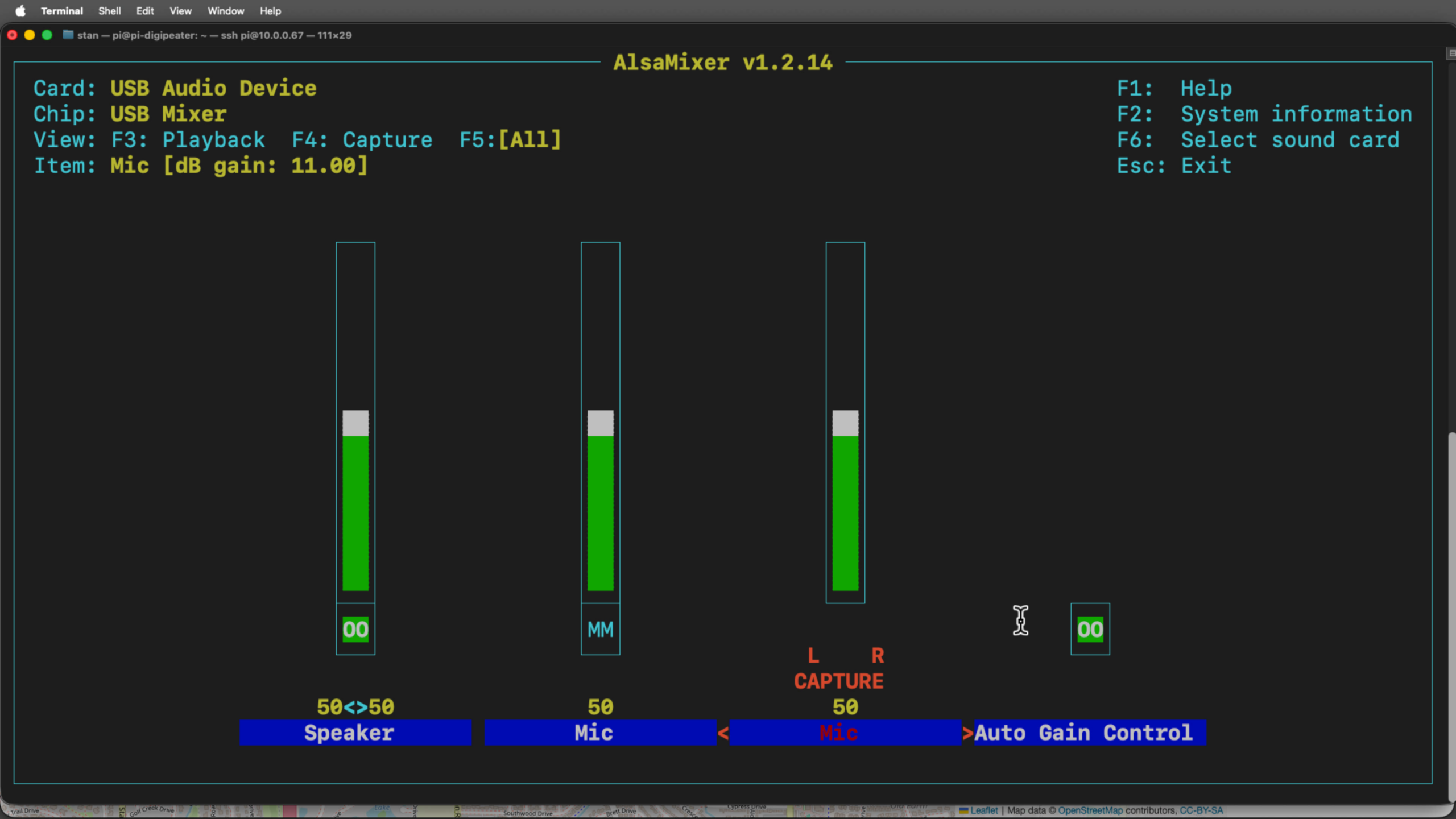
I would suggest setting the levels at 50 as that is what Direwolf recommends. It may take some experimenting to get it right though it doesn’t need to be perfect.
Read-only mode
Since the Raspberry Pi doesn’t have a power switch, it’s not a good idea to constantly remove power from it without shutting it down. If you do that, the microSD card will get corrupted and you’ll have to start all over. You could setup a mini network and remote in and send the shutdown command each time, but I have a different solution. We can force the Pi to boot up in read-only mode. This will keep it from writing to the microSD card so abruptly pulling the power won’t give the card heartburn.
Remote in to the Pi and run the following command.
sudo raspi-config
Choose Performance Options (#4) and then Overlay File System (P2). It will ask if you would like the overlay file system to be enabled, select yes. If successful, it will say the overlay file system is enabled. Select OK to move to the next screen. It will then ask you to write protect the boot partition. Select yes and it will say the boot partition is read-only. Select ok, finish and then yes to reboot the Pi. If you need to make changes in the future, you can reverse this process and enable it again when you are done.
Ready to deploy
If everything went well, you should now have a portable APRS digipeater! I realize there were a lot of steps and commands to make this work. If things aren’t working, double check all your commands. The smallest typo can break the whole thing. If you need a bit more assistance, please reach out to me and I will try to help you. Let me know if you made it this far and got it working on your ID-4100A. Thanks for sticking with me for another tutorial!